Averaging involves accumulating a large number of waveforms (records) and subsequently scaling by the total number of accumulated waveforms. The accumulation functionality is available through the FWATD firmware option. This process effectively suppresses random noise and enhances systematic (periodic) signals.
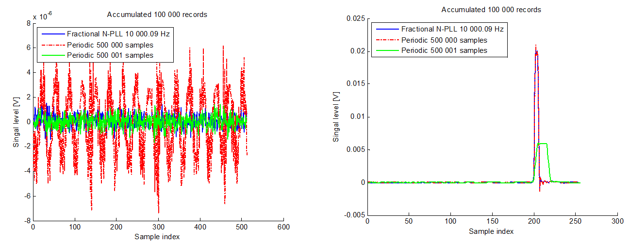
However, when a large number of records are accumulated, systematic noise may become apparent. Refer to the figure below, where the left-hand red curve illustrates accumulated systematic noise at 6 µV. This type of noise is amplified when the trigger is correlated with the noise source.
To mitigate this, decorrelating the trigger frequency from the noise source can suppress the systematic noise. The green and blue curves in the figure demonstrate the resulting noise suppression.
Decorrelation can be achieved through various methods, though care must be taken to avoid introducing jitter. In the right-hand figure, the green pulse exhibits jitter and is broadened as a result. In contrast, the red and blue pulses remain sharp, indicating the absence of jitter.
The ADQ35 and ADQ35-PDRX digitizers incorporate a fractional-N PLL-based trigger source, which enables both systematic noise suppression and low jitter performance, as demonstrated by the blue curves in both plots.
For further details, refer to the application note 25-3162 ADQ35-PDRX FWATD trigger

The application note outlines a method for achieving noise suppression during waveform accumulation. It is recommended for use with the ADQ35 and ADQ35-PDRX devices when accumulating a large number of waveforms.
The method relies on a Fractional-N PLL, which requires the ADQ35 to act as the timing master within the system. This may necessitate some system-level redesign. For scenarios where only the pulse source needs to be triggered, figure 7 in the application note provides a viable solution. If more precisely controlled signals are required, this approach remains applicable but with minor modifications.
In this configuration, the Fractional-N PLL triggers the pulse source and simultaneously serves as a clock reference for an FPGA or microprocessor, the generation of states and control signals as illustrated below.
If the trigger rate is too low to support PLL operation, a higher frequency can be used, with a gating mechanism applied to set the desired trigger rate for the pulse source.
This setup ensures synchronization across all system components, enhancing timing precision and signal integrity.

